VPM 360

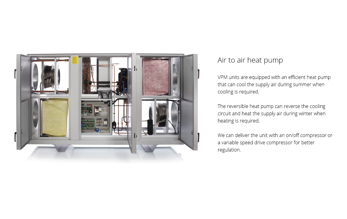
VPM 360 is a ventilation unit with heat recovery via a reversible heat pump that can both cool and heat the supply air. The integral heat pipe increases both the cooling and the heating effect and it therefore ensures a good COP. 

VPM 360 is used for ventilating buildings with a requirement for good air quality, for instance if rooms or spaces with polluted air are ventilated via the central ventilation system. Such spaces could include commercial kitchens, lavatories and changing rooms. Extract air and supply air are kept separate, and particles will therefore not be passed from one to the other.

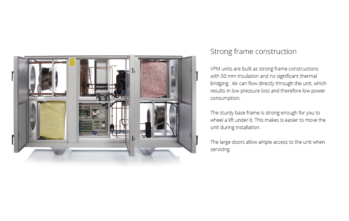
The heat pump is integrated in the unit, and it is therefore a compact unit that does not take up much space in the building. At the same time you avoid having to install an external cooling unit outside on the ground and on the roof. 
 

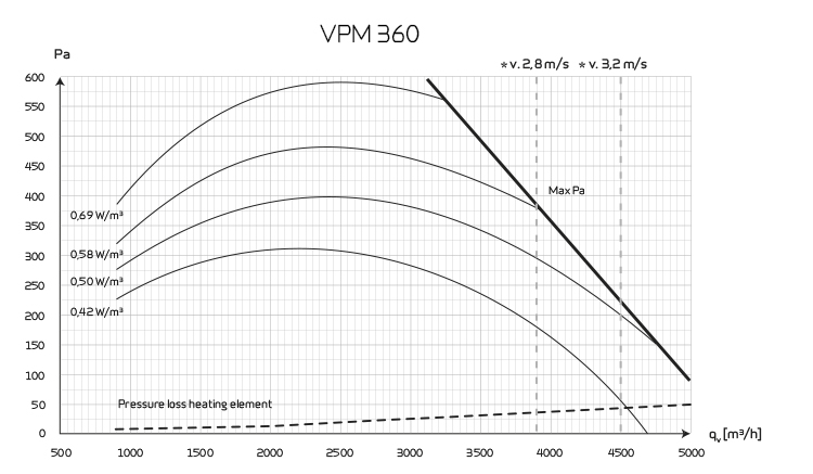
Airflow (see planning data for SEL/SFP values)

Min : 900 m3/h
Max : 4400 m3/h
Dimensions (W x D x H) 2255 x 939 x 1400 mm
Weight 480 kg
Plate type casing Aluzinc steel plate
Fan type Low-energy EC-ventilators with B-wheel
Filter class Standard bagfilter ISO ePM10 >60% (M5) extract air and ISO ePM1 50% (F7) fresh air
Duct connections Ø 500 mm
Condensate drain PVC Ø 20 x 1,5 mm
Power supply 3 x 400V + N, 50 Hz
Max. phase current 6,5 kW / 3 x 16 A (does not include accessories)
Tightness class DS/EN 1886 L2
Refrigerant cooling heatpipe R 744 / 4,5 kg
Compressor on/off, Maneurop type: MTZ
Refrigerant cooling circuit R 407 C / 3,5 kg
Condenser/evaporator (HxW) 600 x 655 mm
Condensation capacity 8,0 l/h (25°C / 70% RH, nominal airflow)


Capacity

Max Pa capacity of standard unit, Pt,ext as a function of qv, with regard to SFP-values.

SFP-values according to EN13053 for a standard unit with ISO ePM10 >60% (M5) & ISO ePM1 50% (F7) filters an no heating element.

* Airflow speed above evaporator is measured at meters per second.

Attention! The SFP values are measured and stated as a total value for both fans.
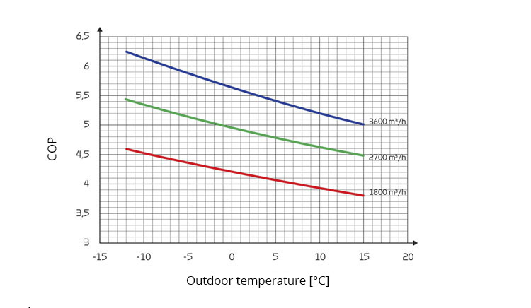
COP (air/air)

Heat effect factor COP [-] supply air as function of outdoor temperature [°C] and volume flow qv [m3/h].

According to EN14511, extract air = 21 °C.
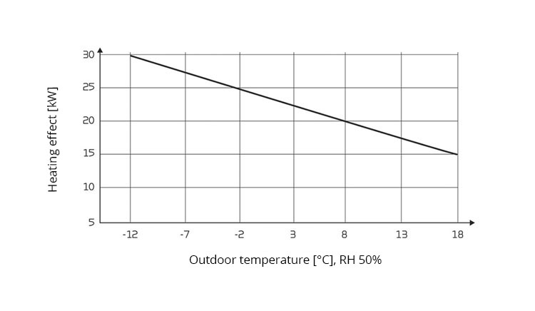
Heat effect

Heat effect Qc [W] as a function of qv 3,600 m3/h and outdoor air temperature [°C].
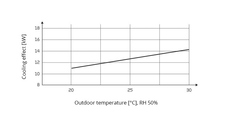
 

Cooling effect

Supply air temperature [°C] as a function of outdoor air temperature [°C] and volume flow qv 3,600 m3/h balanced flow.
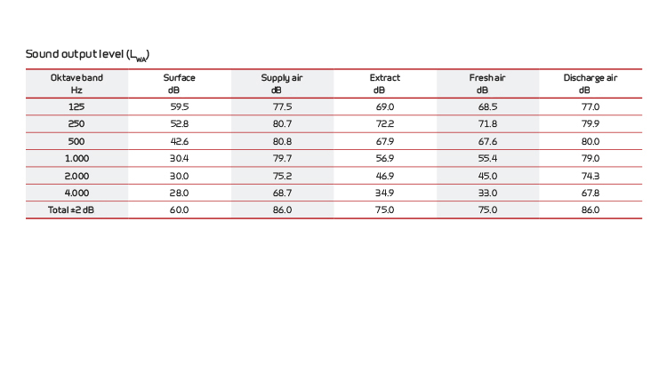


Sound data

Sound data for qV = 3,600 m3/h and Pt, ext = 250 Pa according to EN 9614-2 for surfaces and EN 5136 for ducts.

Sound output level LWA drops with falling air volume and falling back pressure.

Sound output level LpA at a given distance will depend on acoustic conditions in the place of installation.

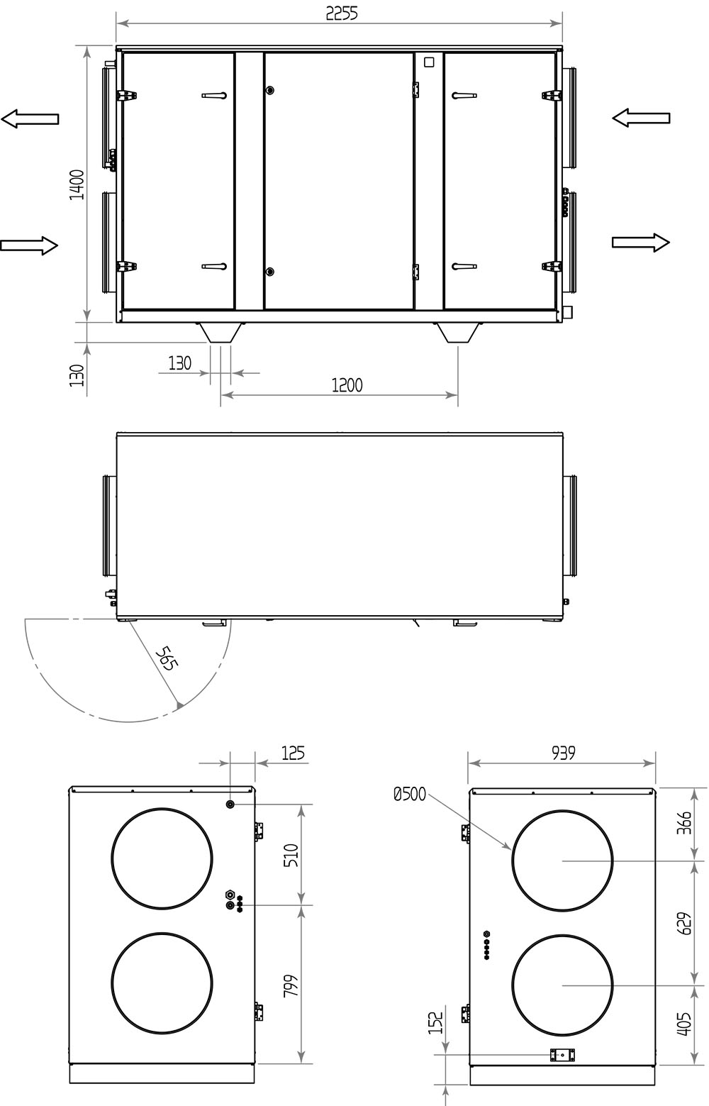
Dimensional drawing VPM 360:

Connections:
1. Outdoor air
2. Supply air
3. Extract air
4. Discharge air

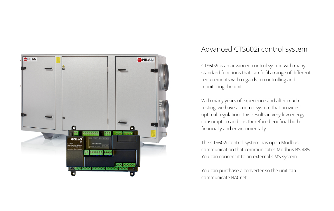
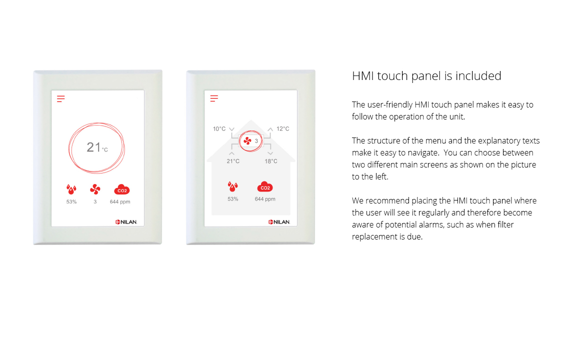
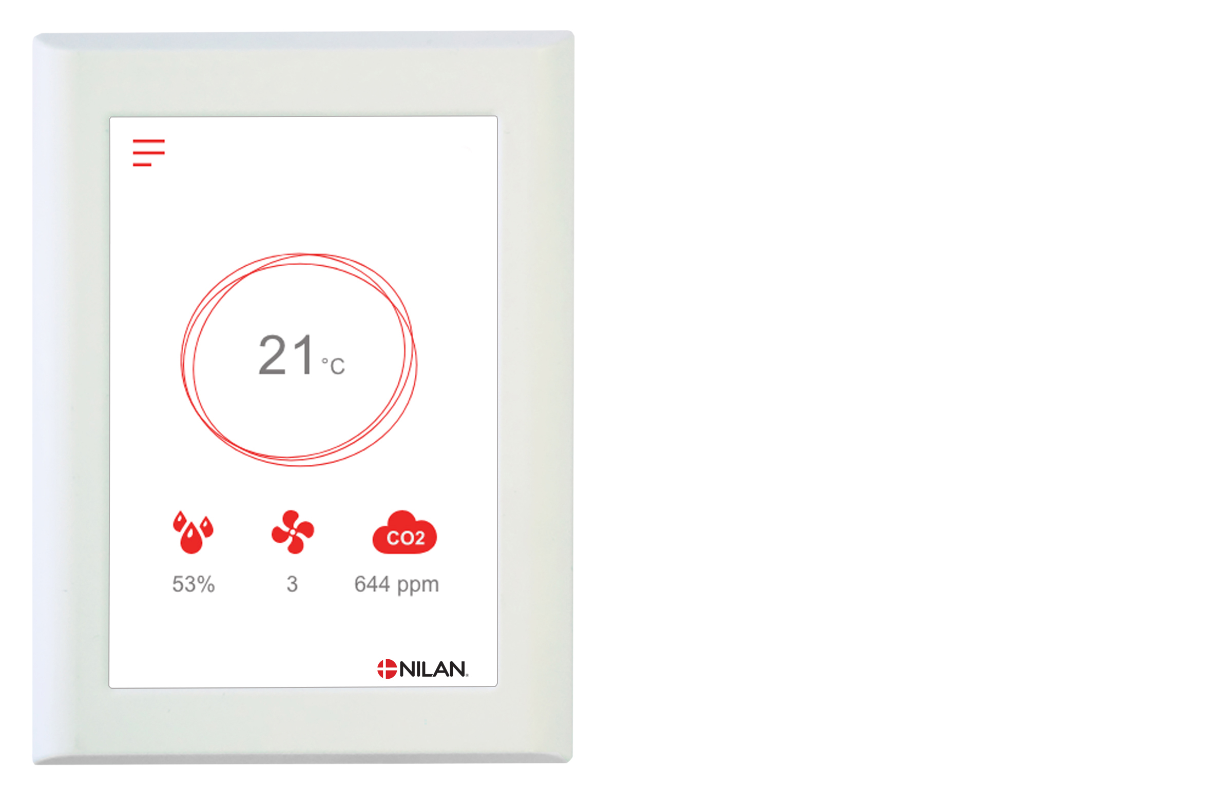
The CTS602 control system is an advanced control system with many settings options. The control system is supplied with factory default settings that can be adapted to the operational requirements in order to achieve best possible operation and utilisation of the unit.

The HMI Touch panel provides an overview of the current operation of the unit, and the structure of its menu makes it easy to navigate for both user and installer. There is an option for selecting between 2 front page images for the main screen.

External communication

The CTS602i control unit communicates by default with Modbus RTU RS485 communication. A CTS system using this form of communication can easily be connected to the unit.

Functions overview   + Standard
- Accessories
Alarms Description of errors indicated with alarms. Alarm log displaying the latest 16 alarms. +
Joint alarm The CTS602 control system has an output signal that is activated in the case of an alarm. It can be connected to, for example, external automation.  
Filter monitor Filter alarm with timer that can be set to 30/90/180/360 days. +
Data display An overview of the current operation with regards to temperatures, fan speed level etc. +
Week program The CTS602 control system has 3 week programs that can be set individually (the default setting is “off”). +
Humidity control Enables a higher or lower degree of ventilation at a high/low level of humidity. -
Air quality Enables you to adjust the degree of ventilation depending on the CO2 level in the air. -
Winter low You can prevent a low level of humidity in the dwelling by activating low ventilation at low outdoor temperatures. +
Temperature regulation Enables you to control the operation of the unit in accordance with the room temperature. +
Summer/winter mode You can set the unit to operate in summer or winter mode.  
Language You can choose from more than 10 languages in the control panel. +
User levels The menu in the control panel is divided into 3 user levels: User/Installer/Factory. +
User selection 1 Enables you to override the operating mode via an external potential free signal. +
Electrical after-heating element An electrical after-heating element allows you to control the supply air temperature. In this way the unit can help heat the dwelling. -
Water after-heating element A water after-heating element allows you to control the supply air temperature. In this way the unit can help heat the dwelling. -
Frost protection In order to protect a potential water after-heating element against frost damage, the unit will stop and display an alarm if the temperature in the water after-heating element becomes too low. -
Air exchange Stepless setting of four fan speed levels. The supply air and the extract air can be set individually. +
De-icing Based on temperature, this automatic function de-ices the counterflow heat exchanger if ice has formed within it. +
Room low Safety function that will cause the ventilation unit to stop if the heating system for the dwelling fails. This will prevent the unit from cooling the dwelling even further. +
External heating The ventilation unit can control an external heat supply in accordance with the current room temperature. +
External fire automation system You can connect the ventilation unit to an external fire automation system or to a fire thermostat. This will signal to the unit whether to stop or continue operation. +
Integral fire automation system The ventilation unit is available with an integral fire automation system that can control fire and smoke dampers. -
Pressure control regulator You can install a pressure sustaining regulator on the side of both the extract air and the supply air. -
Delayed start-up You can activate a delayed start-up of the fans if you install, for instance, a shut-off damper. +
Restore settings You can save the current settings and subsequently restore them if, for instance, the user has altered the settings on the unit. You can also reinstall the default settings. +
Manual operation Different functions can be tested manually. +
Energy saving function You can activate a power saving function of the operation. +
Modbus  You can set the Modbus address of the unit. The default setting is 30. +
Data logging It is possible to log the operational data of the unit every 1 - 120 min. Alarms are logged when they occur. +
Control panel You can choose from 2 different images for the main screen. +

You can find further information about all the functions in the Software and Installation instructions for the unit.


Nilan CTS 6000 enables you to control and monitor Nilan commercial ventilation units online via a computer. You can access your units from anywhere in the world. By using a weekly or annual program, the unit can be set to operate automatically with regards to e.g. operating times, room temperatures, fan speed levels and alarms. 

The CTS 6000 enables you to monitor the operating mode of the unit closely. Whoever it concerns will automatically be notified via email about all types of operational disruptions, alarms, and maintenance notifications. Operational disruptions can then quickly be dealt with and, at the same time, you will safely know when to carry out maintenance and when to plan services. 

Functions
• Online program for controlling and monitoring Nilan’s commercial ventilation units
• Controlling and monitoring unit via computer
• Automatic control via weekly or annual program
• Setting temperature control, night cooling, pressure limits, alarms, fan speed level etc.
• Historical curves for temperature, air volume, heating, and cooling requirements
• Trend curves displaying current operation of the unit
• Automatic alarm notifications via email regarding operating mode, errors and maintenance
• Connection to room thermostats and frequency converters
• Adapting user interface to different user levels

Advantages
• You can control and monitor your units from anywhere in the world
• A weekly or annual program ensures detailed regulation of the indoor climate to meet the requirements of the individual building
• The automatic and intelligent control system ensures optimised operation
• Historical graphs enable you to optimise operation and the indoor climate
• Speedy diagnosis of potential operational disruptions or errors means that they can be dealt with quickly
• Better opportunity to provide remote support and therefore also to plan services
• User friendly control panel where the user interface can be adjusted according to personal preferences

Add-on
You can purchase a LON/Modbus card so you can connect the unit to an external CTS system that communicates LON or Modbus.

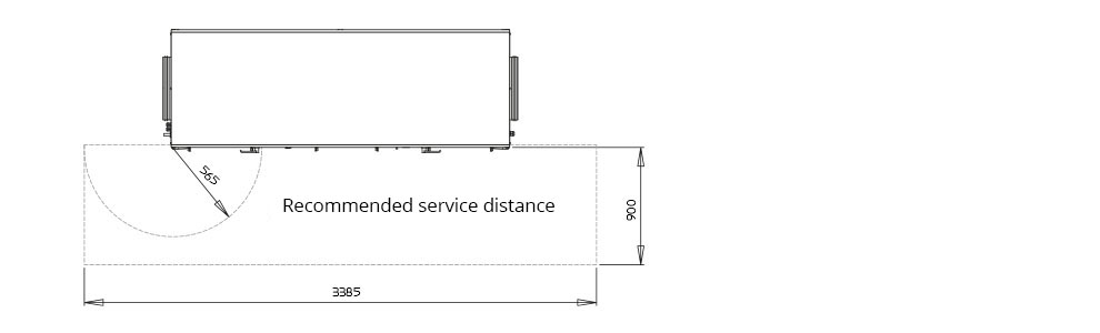
ATTENTION! Good clearance in front of the unit is recommended. When positioning the unit, you should always consider future services and maintenance. It must be easy to replace filters and it must be possible to replace fans or other components. There must be space for easy cleaning of the unit. When cleaning the unit, water may run out of cleaning and condensation drains. There must therefore be space for mounting water locks at condensate drains as well as any.

The unit must be level to enable proper drainage from the condensate tray.

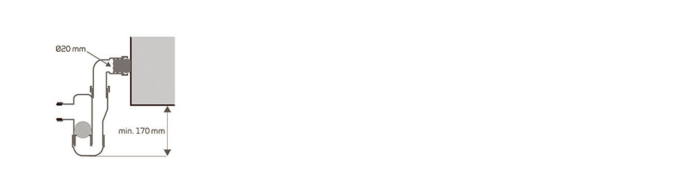
ATTENTION! The unit produces a limited level of noise and vibrations, but you should still take into account potential vibrations that can spread from the unit to individual parts of the building. In order to separate the unit from the underlying surface, it is therefore recommended that you fit vibration absorbers under the unit. There should be approx. 10 mm distance to other building components and to permanent fixtures. 

Condensate drain
Connecting Nilan's water trap with ball at the lower part of the unit / extract air part / suction side.

Motor and motor control

Motor type EC-motor
Motor class according to IEC 60034-30 IE3 (Premium efficiency)
Voltage input 1 x 230 V
Current overload protection Built-in
Control signal 0 - 10 V
Fluid temperature (air) -20 / +40 ºC
Ambient temperature (operating) -20 / +40 ºC

Data for ecodesign

Fan data  
Overall efficiency (A-D) 65,5 %
Measurement category (A-D) A
Efficiency category 62N (2015)
Efficiency in optimal operating point 76,2
   
Motor data (optimal operating point)  
EC-motor With motor controller
Voltage input 1,09 kW
Air flow 3905 m3/h
Pressure increase 530 Pa
Speed 2150

Conditions according to EC327/2011


Accessories