VPM 700 Cleanroom
VPM Cleanroom is a unique ventilation unit with heat recovery. It uses new, ground-breaking, patented technology that prevents supply air from getting into contact with extract air. It does so with great efficiency. This prevents an exchange of microorganisms such as bacteria, particles or other pollutants in the air. As a result, there can be no potential contamination of the supply air.
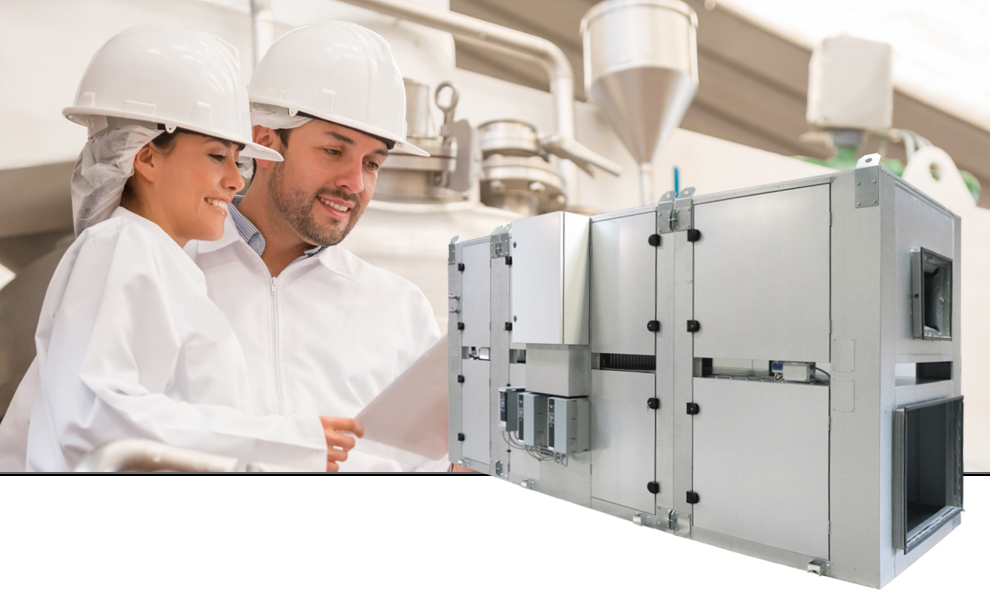
VPM Cleanroom is particularly suitable in relation to businesses and industries that have high requirements to hygiene, such as laboratories, operating theatres and in the food industry.
The VPM Cleanroom unit is a compact construction, and it therefore does not take much space. The unit is delivered as an assembly-friendly modular construction, which makes it easy to install.
Airflow (see planning data for SEL/SFP values)
Min : 5000 m3/hMax : 8900 m3/h

No contamination
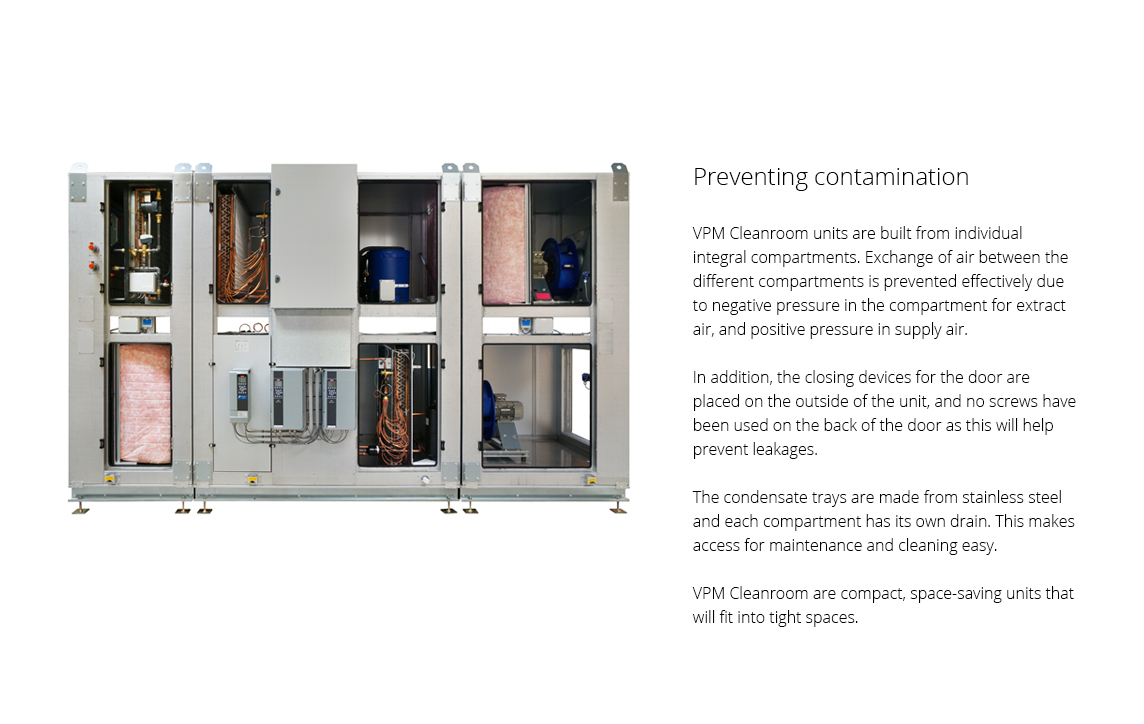
VPM Cleanroom is built from individual compartments, which helps prevent contamination. Each compartment has an integral condensate tray from stainless steel and a drain for condensate water. The division of the unit into individual compartments makes access easy when carrying out maintenance and cleaning.
No screws or blind rivets have been used in the construction of the unit, which helps prevent leakages. The control system and frequency converters are placed on the front exterior of the unit in order to keep all surfaces inside the unit as even and smooth as possible. In addition, a closing mechanism has been developed especially to avoid breaking the evenness of the inner surface of the unit. The smoothness of the surfaces helps minimise the risk of contamination or leakages. It also makes it easier to clean the unit.
The position of the fans ensures that there is positive pressure in the clean side. That way, potential leakages inside the unit will move from clean to unclean air, and not the other way around. In other words, there is positive pressure in the supply air, and negative pressure in the extract air. The purpose is to avoid contamination and spreading of unwanted particles, and also to ensure that the laboratory is clean and the work environment safe.
VPM Cleanroom meets the requirements and standards of the authorities with regards to clearly separated air in ventilation of laboratories and clinically clean environments.
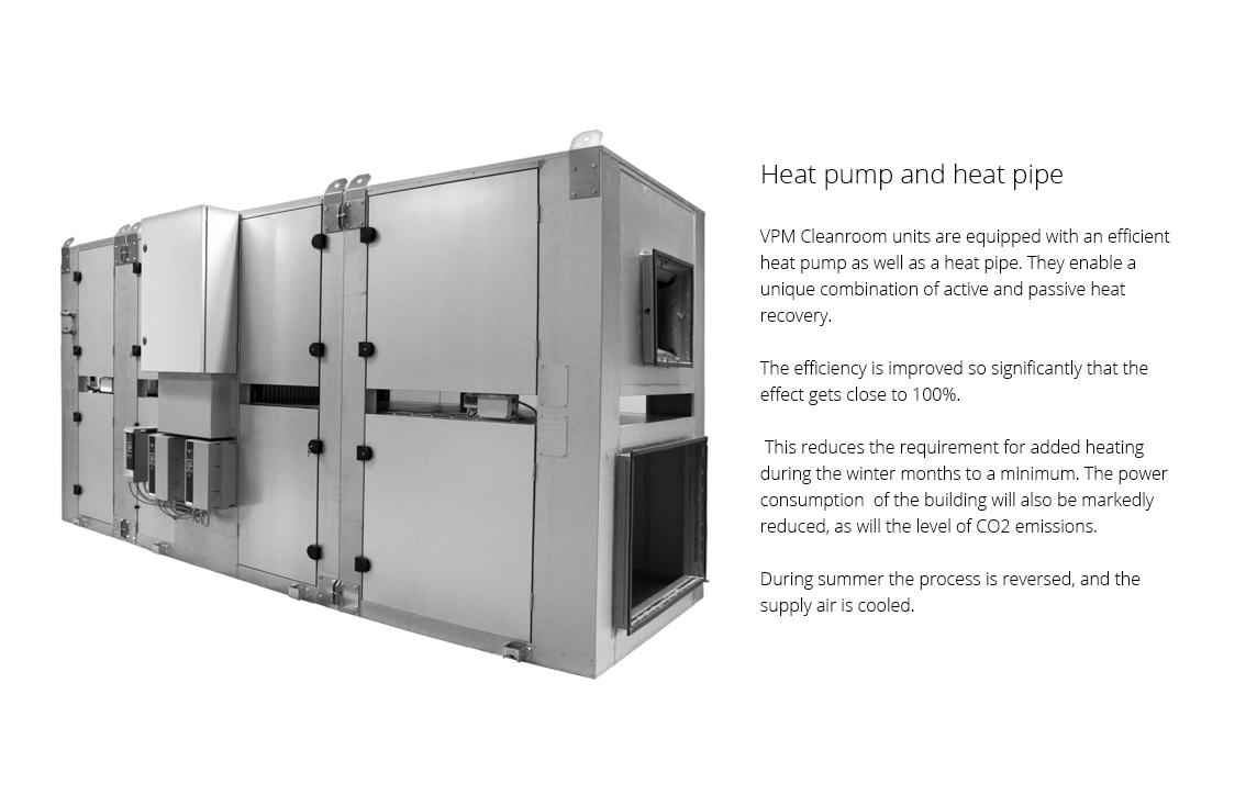
High level heat recovery
Traditionally, run-around heat exchangers have been used for heat recovery in ventilation of cleanrooms. Experience shows that run-around heat exchangers are 40-50 % efficient. In order for traditional units with run-around heat exchangers to meet the regulations by Ecodesign regarding heat recovery, run-around exchanger modules are now combined in series. Regulations require heat recovery of 63% in 2016 and 68% in 2018.
The new ground-breaking and patented VPM Cleanroom solution, which prevents the extract air from getting in contact with the supply air, brings the effect close to 100 %.
Space-saving solution
The patented technology used for VPM Cleanrooms means that the unit requires less space than conventional units. This reduces expenditure on expensive square feet compared to other similar units.
Solutions using conventional units require more space in order to meet current legislation for Ecodesign. European legislation prescribes heat recovery of 63% in 2016 and 68% in 2018.
Since conventional units typically have a heat recovery level of 40 - 50%, it is necessary to combine several modules in order to meet the regulations. A conventional solution therefore means a bigger unit, a larger machine room and higher building costs.
With Nilan’s VPM Cleanroom solution you will save on building costs for the machine room.
|
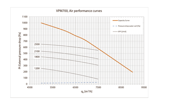
CapacityMax Pa capacity of standard unit, Pt,ext as a function of qv, with regard to SFP-values. SFP-values according to EN13414-7 for a standard unit with ISO ePM10 >60% (M5) & ISO ePM1 50% (F7) filters an no heating element. Attention! The SFP values are measured and stated as a total value for both fans. |
 |
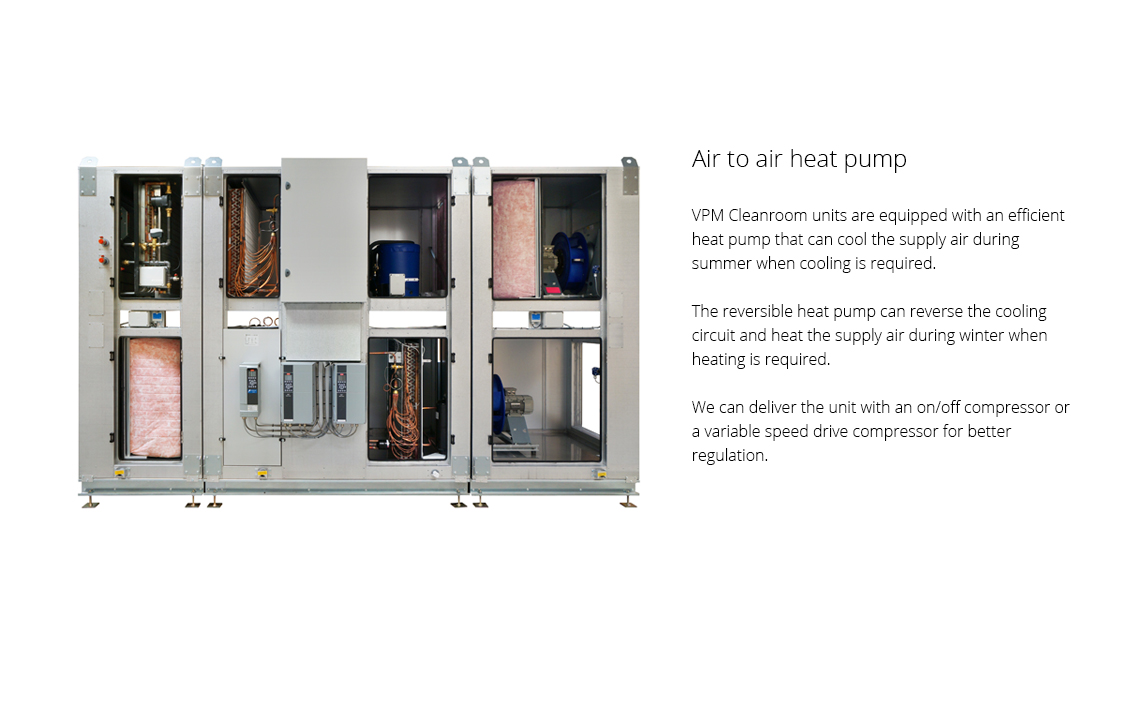
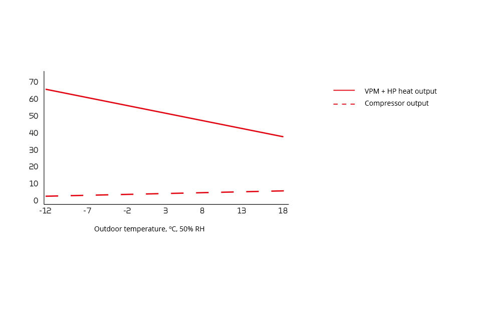
Heat effect (supply air)Heat effect Qc [W] as a function of qv 7,000 m3/h and outdoor air temperature [°C].
|
 |
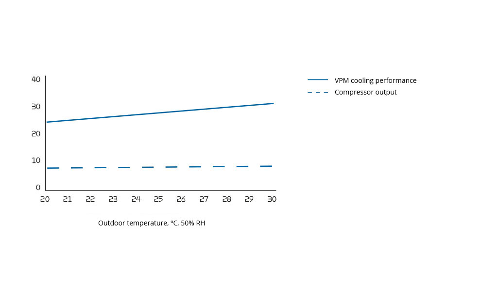
Cooling effectKSupply air temperature [°C] as a function of outdoor air temperature [°C] and volume flow qv 7,000 m3/h balanced flow.
|
 |
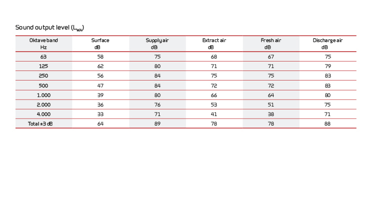
Sound dataSound data for qV = 7,000 m3/h and Pt, ext = 250 Pa according to EN 9614-2 for surfaces and EN 5136 for ducts. Sound output level LWA drops with falling air volume and falling back pressure. Sound output level LpA at a given distance will depend on acoustic conditions in the place of installation. |
 |
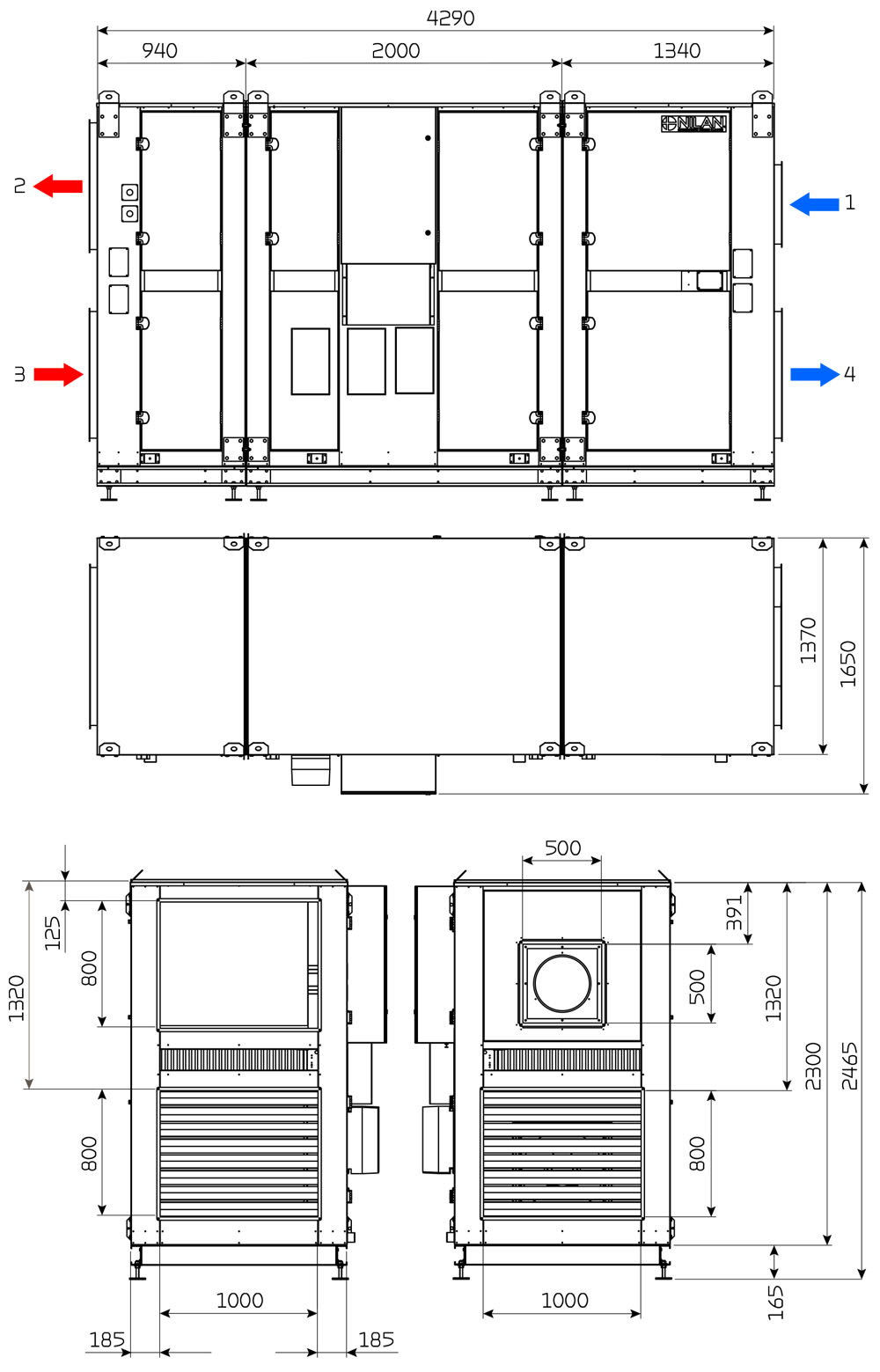
Connections: |
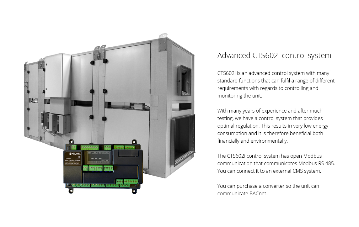
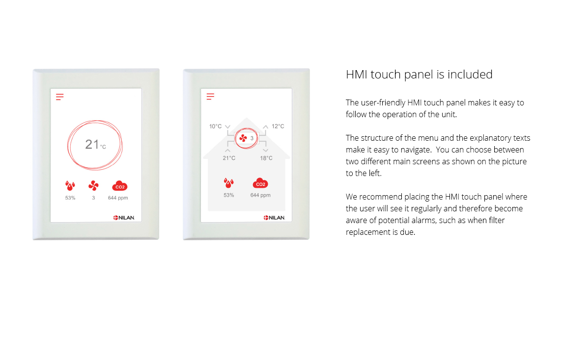
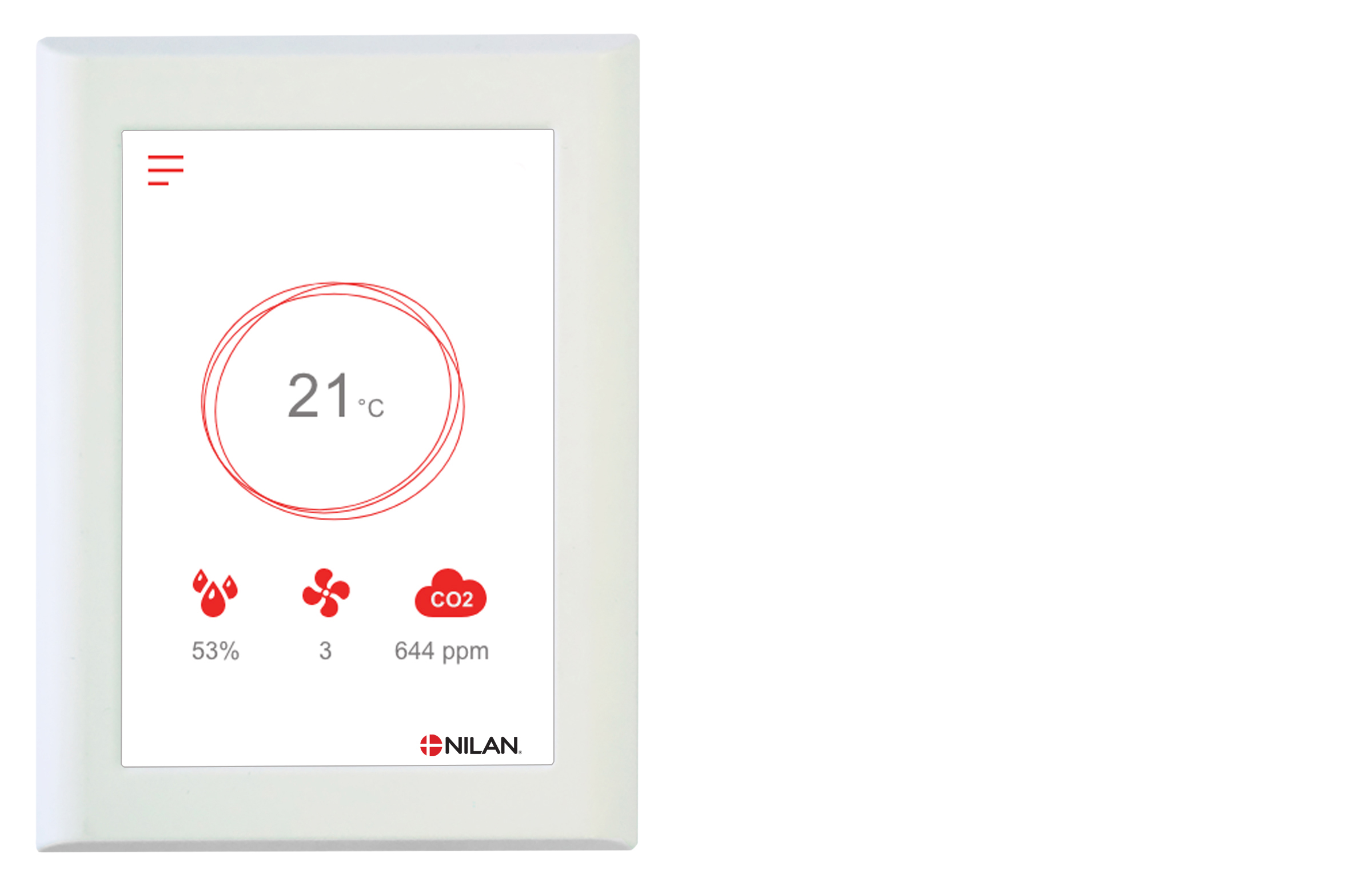
The CTS602 control system is an advanced control system with many settings options. The control system is supplied with factory default settings that can be adapted to the operational requirements in order to achieve best possible operation and utilisation of the unit. The HMI Touch panel provides an overview of the current operation of the unit, and the structure of its menu makes it easy to navigate for both user and installer. There is an option for selecting between 2 front page images for the main screen. External communication The CTS602i control unit communicates by default with Modbus RTU RS485 communication. A CTS system using this form of communication can easily be connected to the unit.
You can find further information about all the functions in the Software and Installation instructions for the unit.
|
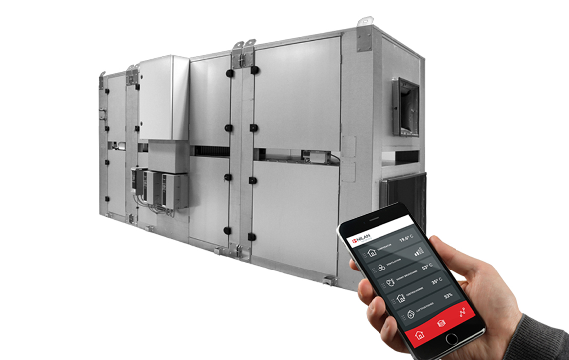
Nilan CTS 6000 enables you to control and monitor Nilan commercial ventilation units online via a computer. You can access your units from anywhere in the world. By using a weekly or annual program, the unit can be set to operate automatically with regards to e.g. operating times, room temperatures, fan speed levels and alarms. The CTS 6000 enables you to monitor the operating mode of the unit closely. Whoever it concerns will automatically be notified via email about all types of operational disruptions, alarms, and maintenance notifications. Operational disruptions can then quickly be dealt with and, at the same time, you will safely know when to carry out maintenance and when to plan services. Functions Advantages Add-on |
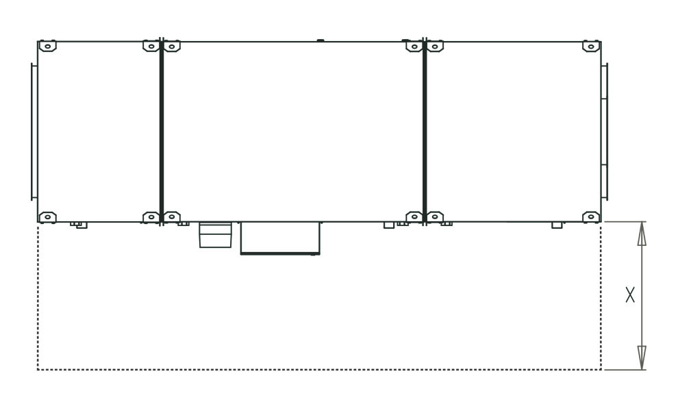
ATTENTION! Leave plenty of free space in front of the unit. When positioning the unit, you should always consider future service and maintenance. You must be able to replace filters easily as well as fans and other components. You must leave enough space so you can clean the unit easily. When cleaning the unit, water may escape the condensate drain. The unit must be level to enable proper drainage from the condensate trays.
Recommended service distance: 1425 mm |