Comfort 1200
Comfort 1200 is a ventilation unit with heat recovery. It is often used for centralised ventilation of residential buildings and for ventilation of schools, offices and commercial buildings.
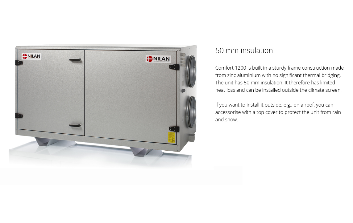
The unit is available in both a right-facing and a left-facing model. It is well insulated and you can therefore install it outside the climate screen. If the unit is to be installed outdoors, you can order a top cover to protect the unit from rain and snow.
All components are carefully selected to maintain the highest level of quality, and they are tested throughout the production process. Once fully built, the units are likewise tested before they leave the factory. The thorough quality control is a reflection of our high standards. Due to these, our products last for many years.
Airflow (see planning data for SEL/SFP values)
Min : 400 m3/hMax : 1675 m3/h

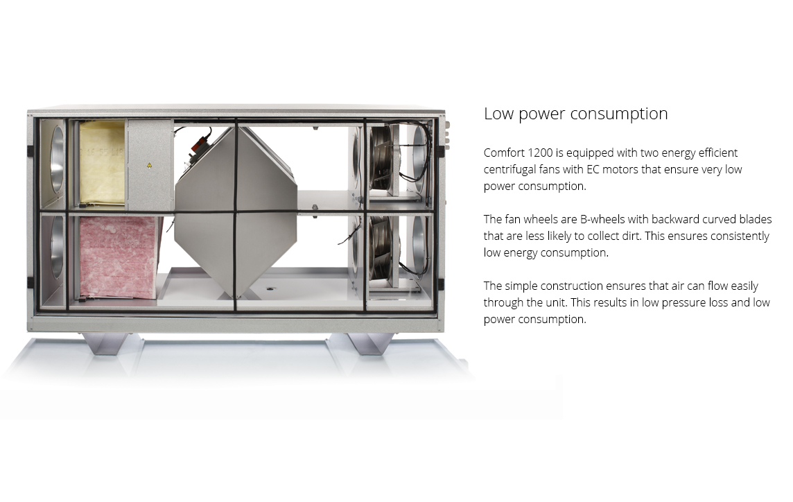
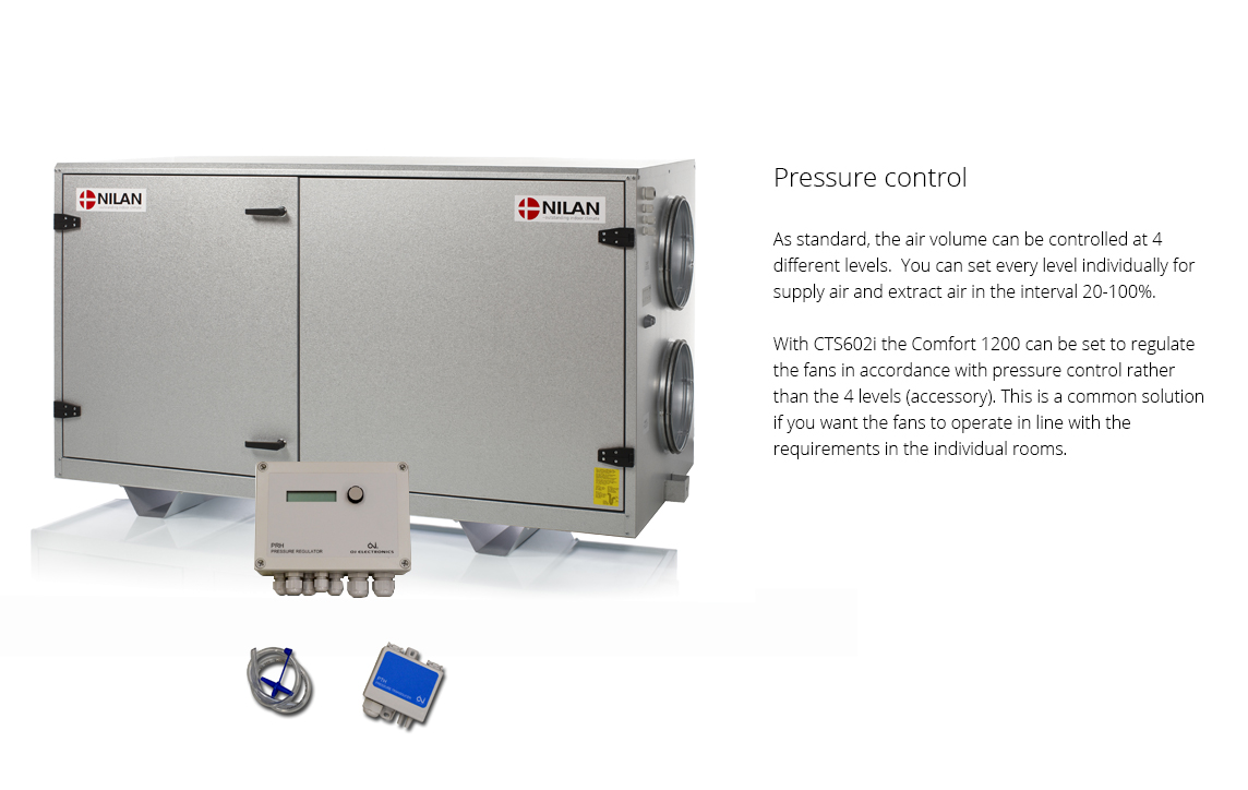
Motor and motor control
|
CapacityCapacity of standard unit as a function of qv and Pt ext. SFP values according to EN 13141-7 are for standard units with ISO ePM10 >60% (M5) filter in extract air, ISO ePM1 50% (F7) filter in fresh air and no heating element. SFP values comprise the unit´s total power comsumption incl. control. Attention! The SFP values are measured and stated as a total value for both fans. |
.jpg) |
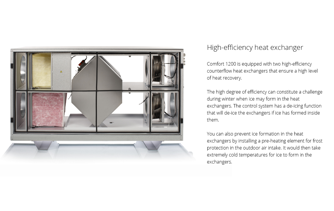
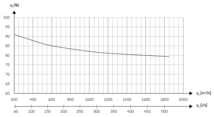
Temperature efficiencyTemperature efficiency for unit with counterflow heat exchanger according to EN308 (dry). Temperature efficiency EN308: ɳ t = (tsupply air-tfresh air)/(textract air-tfresh air) |
 |
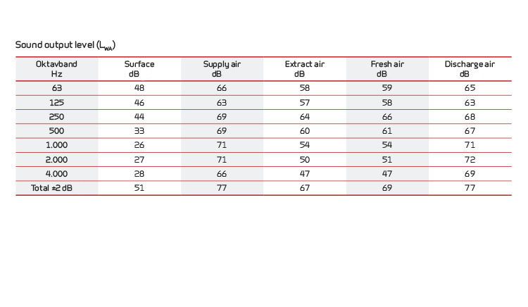
Sound dataSound data for qv = 1200 m3/h and Pt ext = 250 Pa according to EN 9614-2 for surfaces and EN 5136 for ducts. Sound output level LWA drops with falling air volume and falling back pressure. Sound output level LpA at a given distance will depend on acoustic conditions in the place of installation. |
 |
Dimensional drawing Comfort 1200 (Right version)
All dimensions are in mm. Connections |
.jpg)
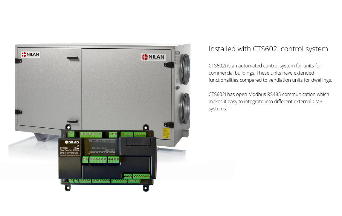
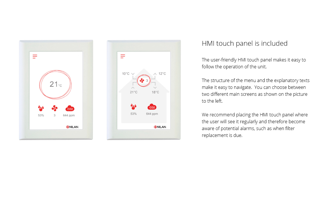
The CTS602i control system is an advanced control system with many settings options. The control system is supplied with factory default settings that can be adapted to the operational requirements in order to achieve best possible operation and utilisation of the unit. The HMI Touch panel provides an overview of the current operation of the unit, and the structure of its menu makes it easy to navigate for both user and installer. External communication
You can find further information about all the functions in the Software and Installation instructions for the unit.
|
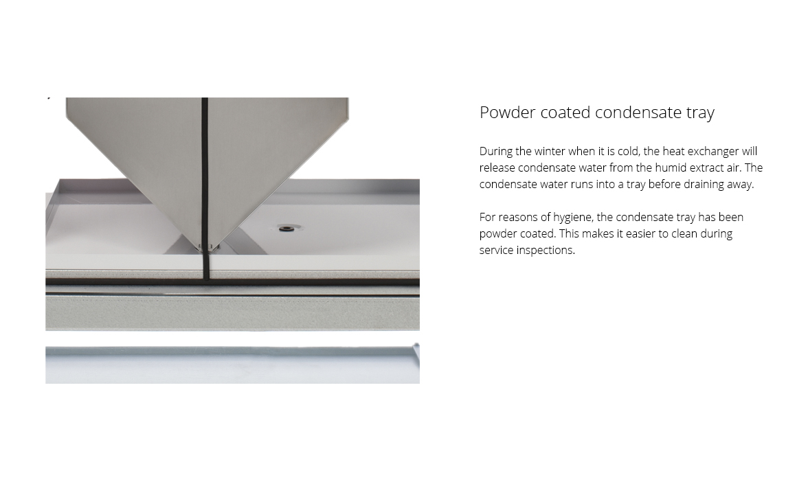
ATTENTION! When positioning the unit, you should always consider future services and maintenance. It is recommended that you leave a minimum of 90 cm of clear space in front of the unit. It must be easy to replace filters and it must be possible to replace, for instance, fans and other components. ATTENTION! The unit must be level to enable proper drainage from the condensate tray.
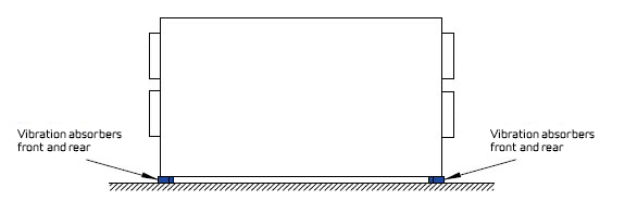
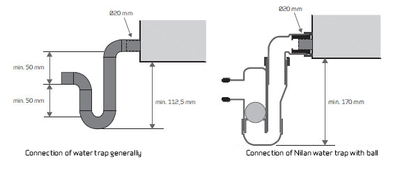
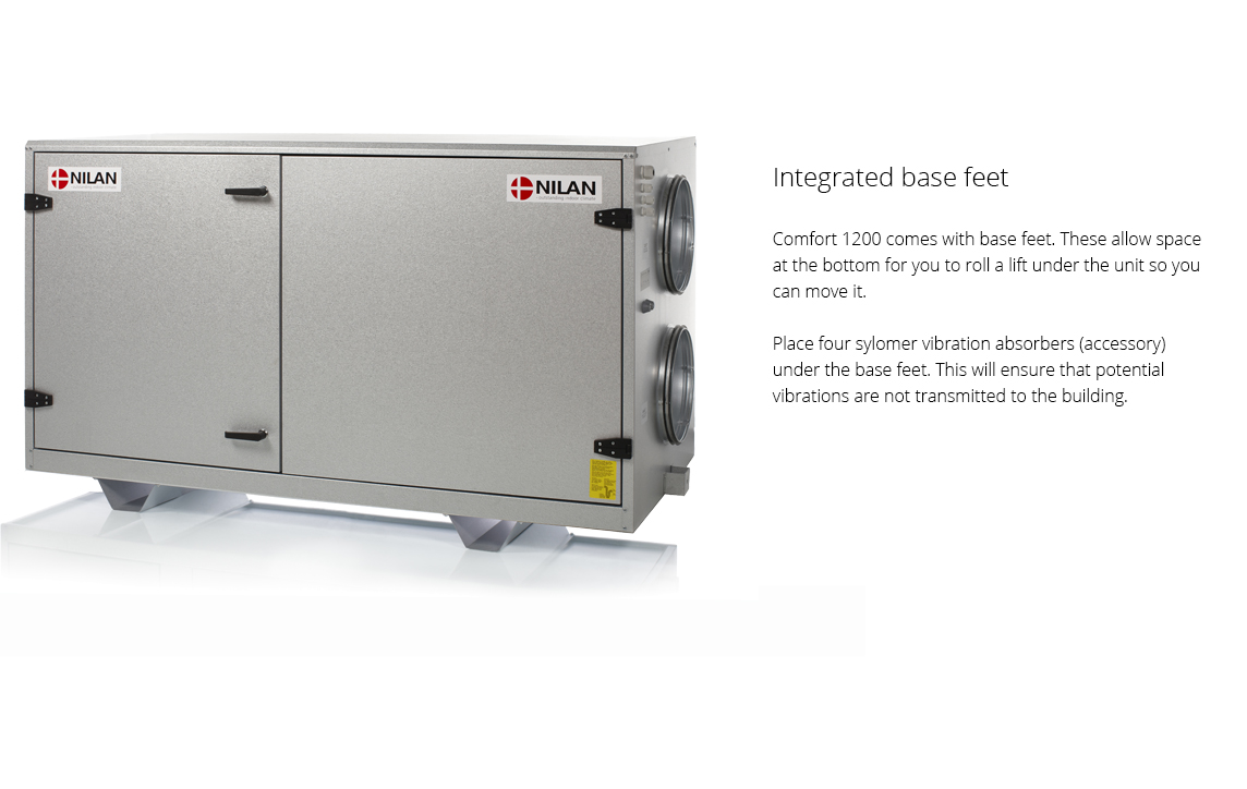
The unit makes little noise and produces only weak vibrations, but you should still take into account potential vibrations that can spread from the unit to individual building components. In order to separate the unit from its foundation, it is therefore recommended that you install vibration absorbers under the unit. There should be approx. 10 mm distance to other building components and to permanent fixtures. Condensate drainATTENTION! You MUST install a water trap in connection with the condensate drain to ensure that condensate water can drain away. If you set up the unit outside the climate screen, it is important to use a heating cable to prevent the condensate drain from icing up. Frost protection of the unit is the installer's responsibility.
|