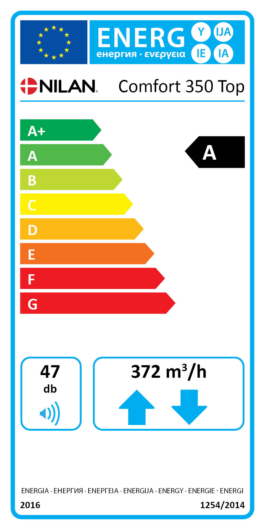
Comfort 350 Top
The Comfort 350 Top is an energy efficient ventilation unit, offering heat recovery for homes and smaller commercial buildings with ventilation requirements of up to 372 m3/h.
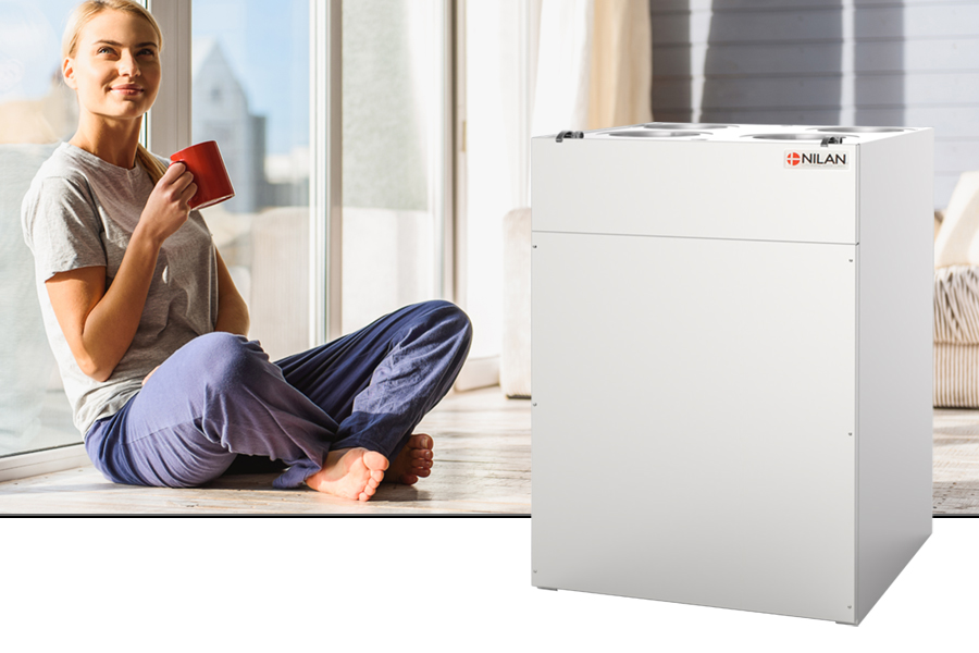
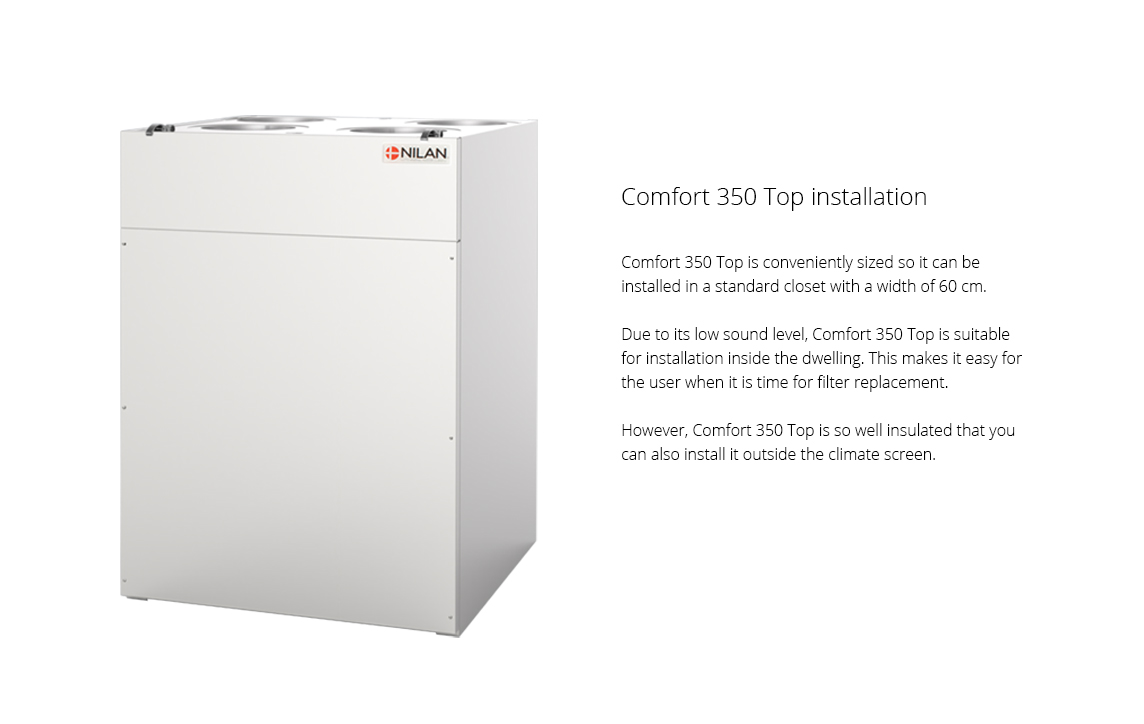
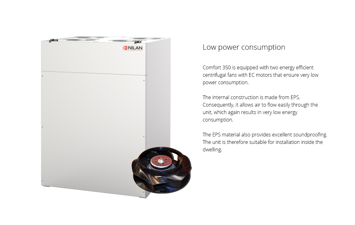
The unit is suitable for installation inside the dwelling as the connections are placed on top of the unit and it has a very low sound level. Its white exterior means that it sits naturally with other domestic appliances in the utility room or machine closet. Comfort 350 Top is a system with compact dimensions, fitting into standard cabinets (60 cm).
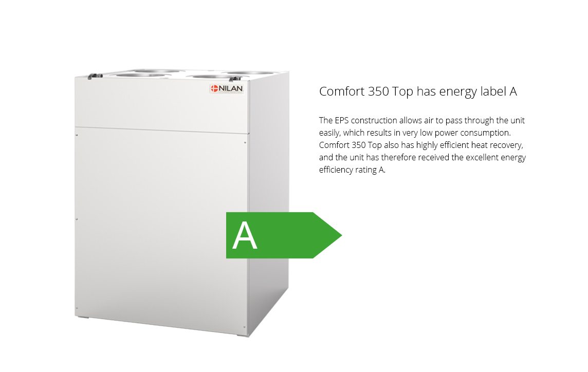
Comfort 350 Top is built to ensure low power consumption and a high level of heat recovery. This combination means that the unit has been given energy label A.
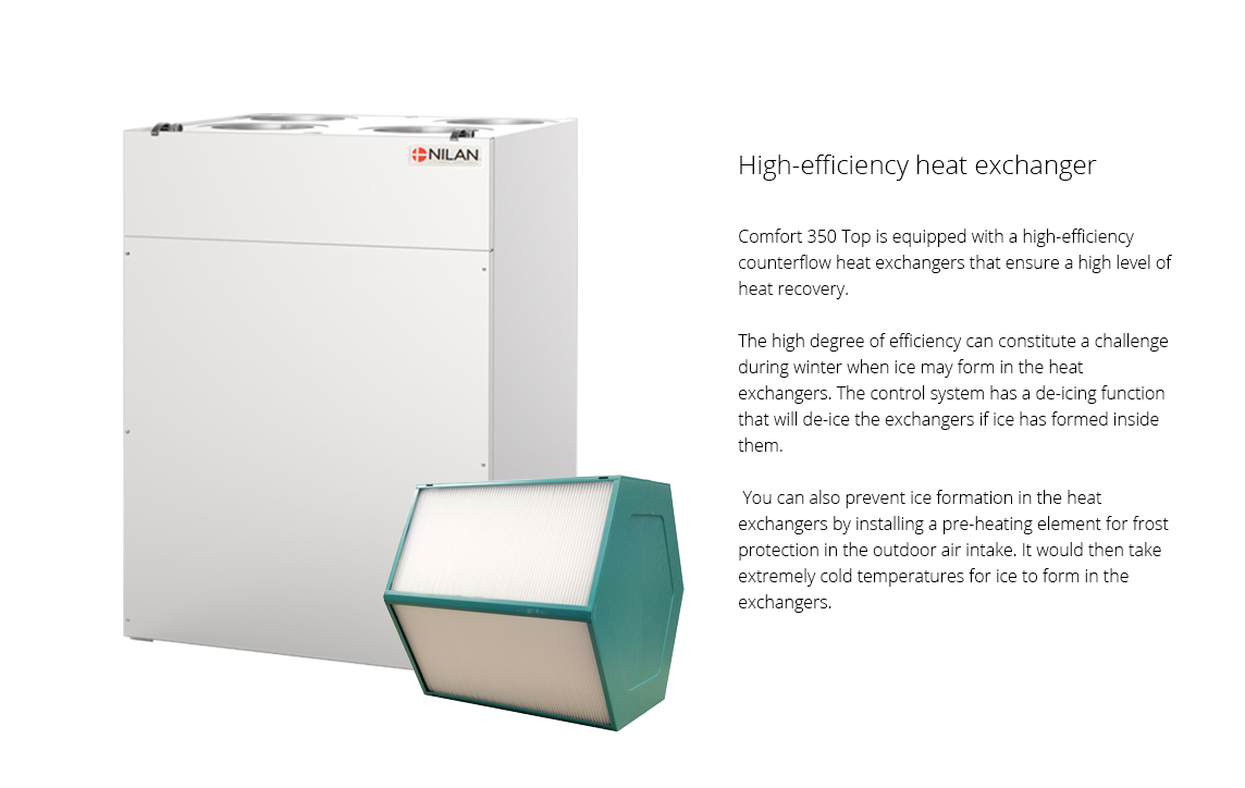
Comfort 350 Top is also available in a Polar version, which is equipped with a self-regulating preheating element. The preheating element protects the unit in cold outdoor temperatures by heating the supply air and preventing frost formation in the heat exchanger.
Airflow (see planning data for SEL/SFP values)
Min : 0 m3/hMax : 372 m3/h
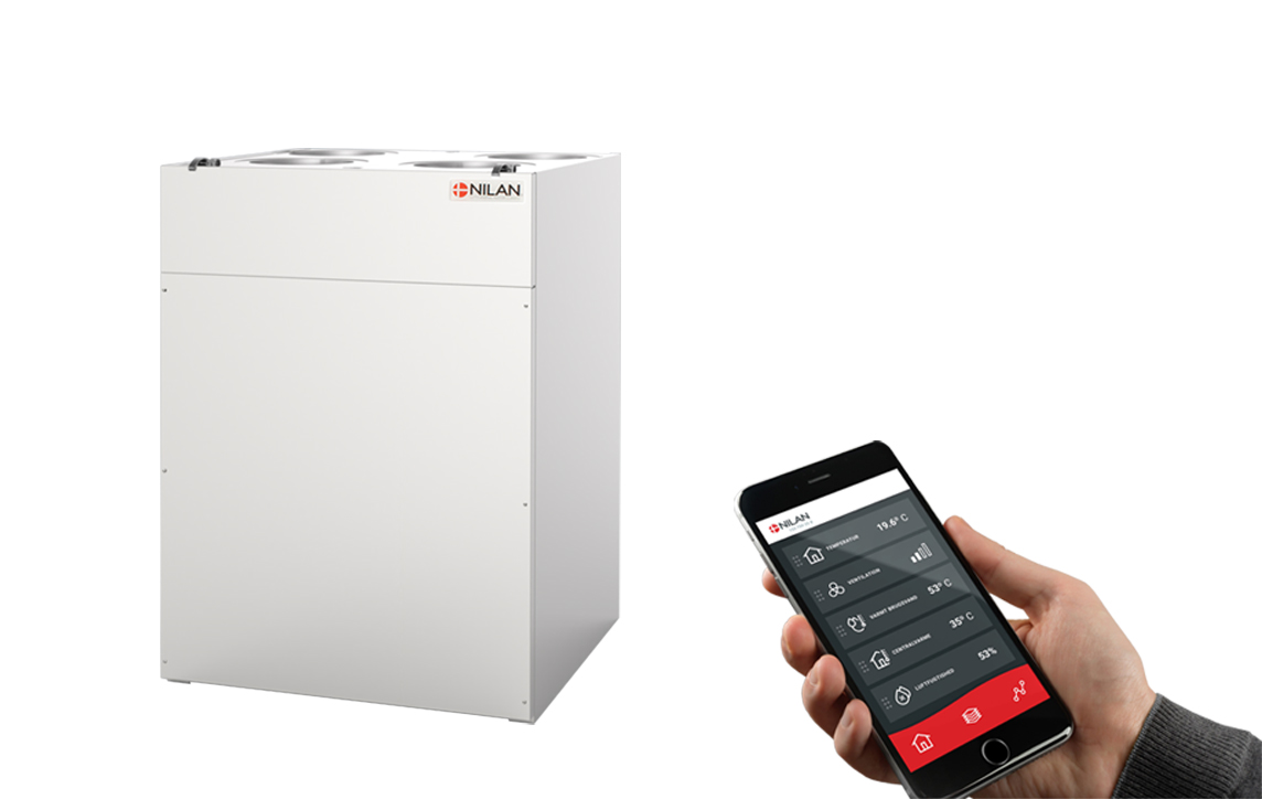

Nilan App - Control the ventilation and heat pump directly from the mobile phone
|
Nilan has developed an App with great features where the user can control the ventilation and heat pump directly from the mobile phone. The App is intuitive, easy and safe to use, and allows the user to e.g. set the room temperature. More ventilation units can be connected using the same App to control the indoor climate in e.g. both the dwelling and the holiday home. More users can be connected the same App. When purchasing a Nilan gateway, the user can access the unit via the Nilan App. Get more information on the Nilan App
|
|
|
CapacityCapacity of standard unit as a function of qv and Pt ext SEL values according to EN 13141-7 are for standard units with ISO 16890 Coarse 75% (G4) filters and without heating element. SEL values represent the unit’s total power comsumption for both ventilator, excl. control. Testet according to EN13141-7 Attention! The SEL values are measured and stated as a total value for both fans. |
.jpg) |
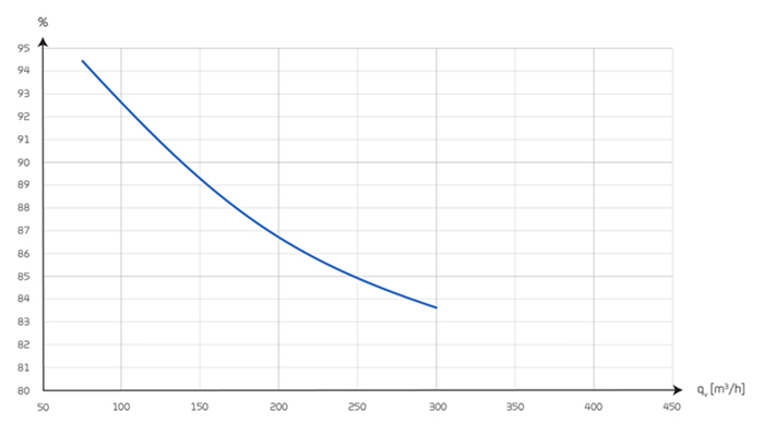
Temperature efficiencyTemperature efficiency for units with counterflow heat exchanger according to EN13141-7 (dry). |
 |
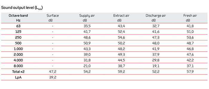
Sound dataSound data for qv = 200 m3/h and Pt ext = 100 Pa according to EN3744 for surfaces and EN 5136 for ducts. Sound output level LWAdrops with falling air volume and falling back pressure. Sound pressure level LpA at a distance of 1 m from the system. |
 |
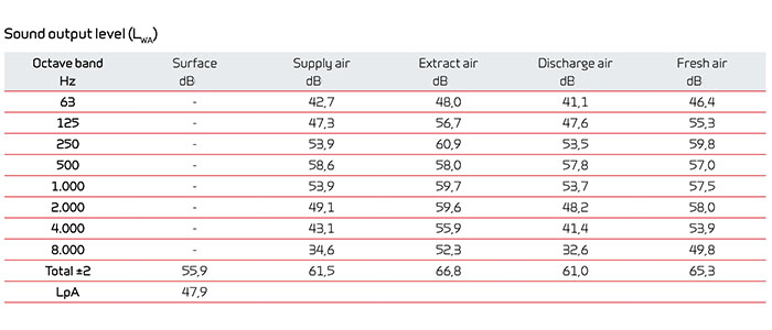
Sound dataSound data for qv = 350 m3/h and Pt ext = 100 Pa according to EN3744 for surfaces and EN 5136 for ducts. Sound output level LWA drops with falling air volume and falling back pressure. Sound pressure level LpA at a distance of 1 m from the system. |
 |
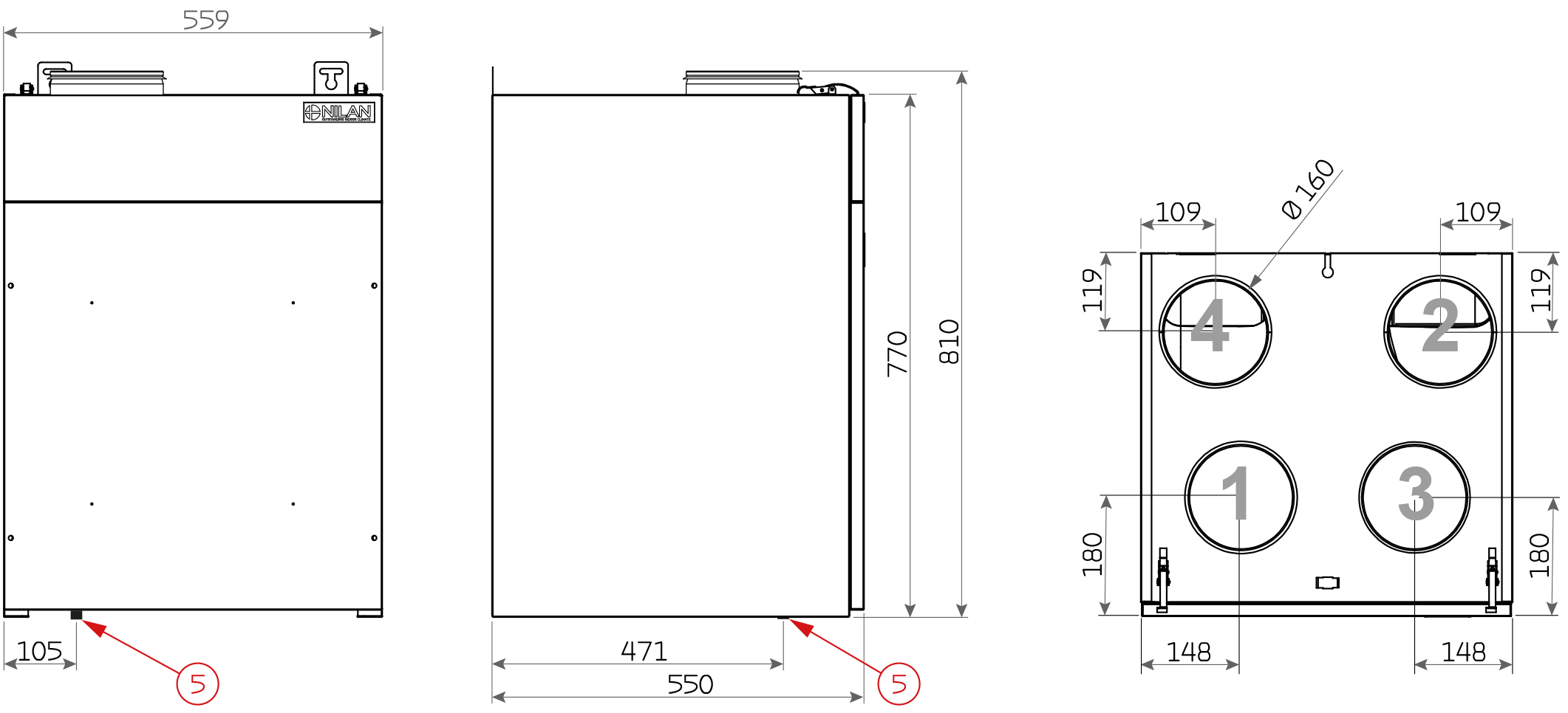
You can download AutoCad or Revit drawings with BIM data on several Nilan ventilation and heat pump solutions - the list is constantly being expanded. Click here to get more about BIM data on Nilan units Dimensional drawing Comfort 350 Top (Right version)
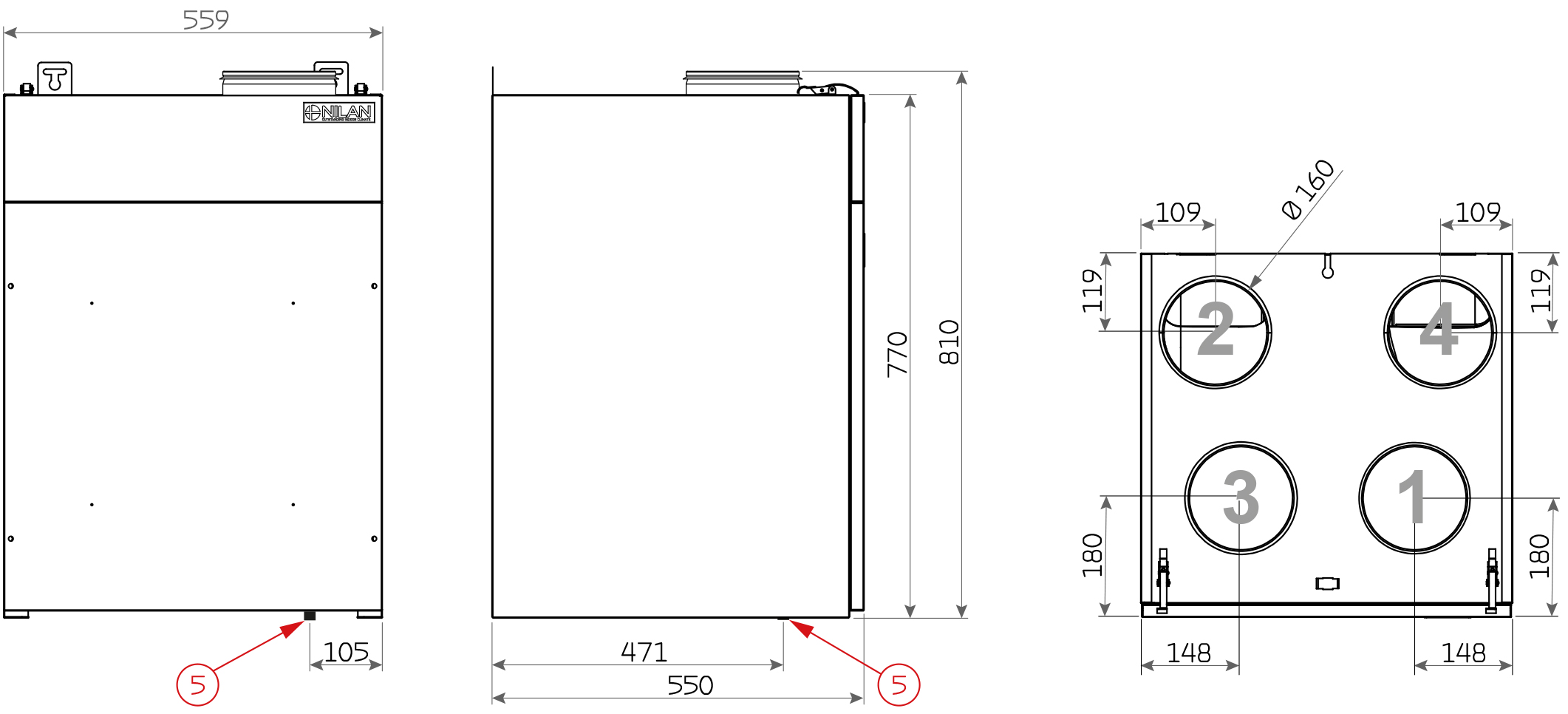
Dimensional drawing Comfort 350 Top (Left version)
All dimensions are in mm. Connections:
Dimensional drawing Comfort 350 Top Polar (Right version)
Dimensional drawing Comfort 350 Top Polar (Left version)
All dimensions are in mm. Connections: |


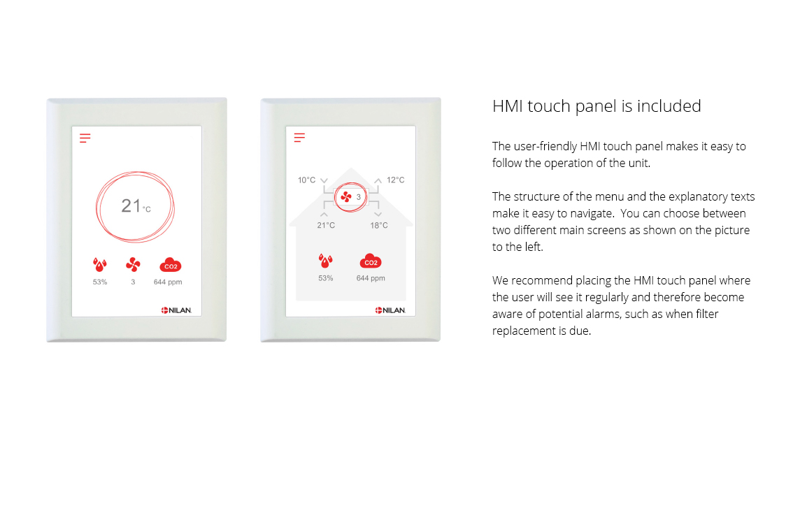
The CTS602 control system is an advanced control system with many settings options. The control system is supplied with factory default settings that can be adapted to the operational requirements in order to achieve best possible operation and utilisation of the unit. The HMI Touch panel provides an overview of the current operation of the unit, and the structure of its menu makes it easy to navigate for both user and installer. External communication
You can find further information about all the functions in the Software and Installation instructions for the unit.
|
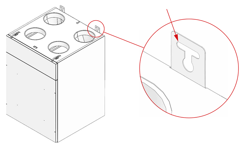
ATTENTION! When positioning the unit, you should always consider future services and maintenance. An open space of minimum 60 cm in front of the unit is recommended. It must be easy to change filters, and it must, for instance, be possible to remove the heat exchanger, and to replace fans or other components. ATTENTION! The unit must be level to enable proper drainage from the condensate tray. The unit is equipped with mounting brackets with holes for wall mounting at the top back of the unit.
|